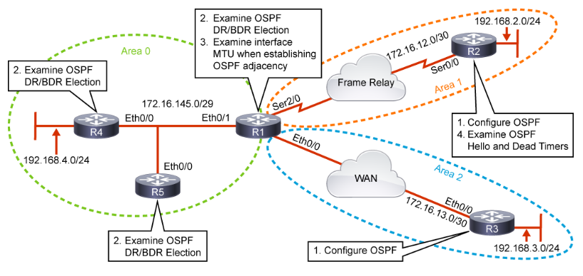
Configure OSPF. A branch router in Area 2 is configured for neighbor relationship with an ABR in Area 0. Note the following:
- Network statements use wildcard masks, and administrators are responsible for ensuring there is no overlapping network information therein.
- Router ID is selected in the following order: (1) statically configured, as seen below; (2) highest active loopback address; (3) highest active non-loopback address.

Note that if a Router ID is manually configured/selected after the neighbor relationship has loaded, it must be manually cleared with the clear ip ospf <process No.> process command. This will cause an outage.


Here is a view of the command show ip ospf neighbor as seen from the ABR in Area 0. The information here is explained as follows: Neighbor ID (the Router ID of the OSPF neighbor); Pri (the Priority used for DR election); State (the OSPF establishment state with comment about DR status, eg. DR or BDR); Dead Time (the timer for neighbor relationship termination if hello LSA is not received before expiry); Address (the address of the neighbor router’s connected interface); Interface (the local router’s interface to the neighbor relationship).
The show ip ospf neighbor output lists the status of the neighbor as DR, BDR, or DROTHER (not a DR/BDR).

Output of the show ip ospf interface command:

Output of the show ip ospf route command. This shows intra and inter-area routes:

DR (Designated Router) and BDR (Backup Designated Router) Election. Why is this important? On multi-access network segments where there are multiple OSPF neighbors, the amount of overhead attributed to a full-mesh exchange of LSDB information can quickly become unwieldy. In this scenario, a centralized router and backup are elected to handle the transfer of LSAs to the mesh. There are two benefits:
- Reduction of routing update traffic. Routers are only required to send link-state information to their DR and BDR via multicast address 224.0.0.6 (the AllDRRouters multicast group), and this information is subsequently flooded by the DR. (Note the BDR receives a copy but takes no action unless the DR fails.) This reduces the amount of update traffic between routers.
- Manages link-state synchronization. The DR and BDR are solely responsible for ensuring that routers have a common copy of the topology. This reduces the frequency of errors.
DR election is based upon the (highest) priority field in the OSPF hello packet. If there is a tie, the highest Router ID between the two wins.
Also note that the DR and BDR roles do not change just because a router with a higher priority joins the topology, only when a DR or BDR fails. (Also, a router with priority 0 will never participate in the election process.)
NBMA Network Considerations

In NBMA networks, neighbors cannot dynamically discover each other. Neighbors must be statically defined using the neighbor <ip address> command in the router ospf configuration mode. Furthermore, the hub router should be statically configured as the DR, and spoke routers should never be candidates for the DR/BDR role (eg., configure with priority 0).
Importance of MTU
Mismatched MTUs can lead to an inconsistent OSPF database. OSPF requires that MTUs match on both sides of the link, and if not, they are stuck in the EXSTART adjacency state.


OSPF Timers. Here are some important facts about OSPF timers:
- To form an adjacency, OSPF hello and dead interval timers must match.
- Hello Timer Values (default):
- Broadcast and P2P links = 10 seconds
- All other OSPF network types, such as NBMA = 30 seconds
- Default dead timer is four times the hello interval. (If a new hello timer is configured but a new dead timer is not, it will automatically set itself to four times the new hello timer.)
- Use debug ip ospf hello to see a mismatch in timers
